Connecting a solid fuel and gas boiler in one system. Scheme of connecting two boilers to one heating system Install 2 boilers in the boiler room
A feature of solid fuel boilers is the need to load firewood to maintain heat in heating appliances, this requires constant attention from the residents. The solution to the problem in such a situation can be called connecting a heat accumulator, installing an additional boiler in the heating system, or using two boilers at the same time: solid fuel and gas.
In this case, heat is supplied to the batteries if the firewood in the firebox has already run out, but there is gas in the cylinder. As alternative you can install a wood-gas unit that does not require special costs and efforts to installation work. But practical use showed that connecting two boilers to one system is much more efficient and profitable. When connecting a gas and solid fuel boiler at the same time, the system is in the mode permanent job even if one of the devices fails. The breakdown of the boiler, which runs on gas and wood, leads to a shutdown of the entire system and it becomes cold in the rooms.
What is the difficulty of connecting two boilers
The main difficulty in using two boilers in one heating system is the need to equip different types strapping. Two gas boilers in one house can only be installed with a closed heating system. That is, connecting a gas boiler to the heating system will not cause problems. And for solid fuel units you need open system. The fact is that the second version of the boiler is capable of heating water to a very high temperature, which leads to an increase in pressure in the system. Even with weak combustion of coals, the coolant continues to heat up.
In such a situation, pressure relief in the heating network is required, for which they cut into the circuit expansion tank open type. If the volume of this element of the system is insufficient, a separate pipe can be brought into the sewer to drain excess coolant. However, the installation of such a tank can cause air to enter the coolant, which can damage the internal elements of the gas boiler, pipes and heating devices.

To avoid all these difficulties of connecting two boilers to one heating system at the same time, you can use two options:
- Use a heat accumulator - a device that allows you to combine a closed and open heating system.
- Organize a closed heating circuit for a solid fuel and pellet boiler using a special security group. In this case, the units can work autonomously and in parallel.
Arrangement of a heating system with a heat accumulator
The use of such an element in a scheme with two boilers in one heating system has several features, depending on the installed units:
- The heat accumulator, gas boiler and heating devices form a single closed system.
- Solid fuel boilers running on wood, pellets or coal heat water, thermal energy transferred to the heat storage. It, in turn, heats the coolant circulating in a closed heating circuit.

For self-creation heating schemes with two boilers, you must purchase the following:
- Boiler.
- Heat accumulator.
- Expansion tank of the appropriate volume.
- Hose for additional removal of the coolant.
- Shut-off valves in the amount of 13 pieces.
- pump for forced circulation coolant in the amount of 2 pieces.
- Three-way valve.
- Water filter.
- Steel or polypropylene pipes.

Such a scheme is characterized by operation in several modes:
- Transfer of thermal energy from a solid fuel boiler by means of a heat accumulator.
- Heating water with a solid fuel boiler without using this device.
- Receiving heat from a gas boiler connected to a gas cylinder.
- Connecting two boilers at the same time.
Assembly of an open type system with a heat accumulator
This type of organization heating system is carried out according to the following scheme:
- Shut-off valves are installed on two fittings of a solid fuel boiler.
- Connect the expansion tank. At the same time, its location should be located on the very high level relative to other elements of the heating circuit.
- Taps are also installed on the pipes of the heat accumulator.
- Connect the boiler and the heat accumulator through two pipes.
- Two tubes are cut into the circuit between the heat accumulator and the boiler, stepping back a short distance from the taps. Shut-off valves are also installed on these tubes. Additional tubes will allow heating the coolant from a solid fuel boiler without using a heat accumulator.

- Next, a jumper is cut in to connect the supply and return pipes in the gap between the heat accumulator and the boiler. Welding or fittings can be used to fasten the jumper to the supply; the jumper is fixed on the return pipe by means of a three-way valve. In the formed small circle, the coolant circulates until its temperature reaches 60 degrees. With stronger heating, the water begins to move in a large circle, capturing the heat accumulator.
- Connect the water filter and circulation pump. Both devices must be installed on the return pipe of the heating circuit, the gap between the boiler and the three-way valve is considered the best place. Here they have a tap with a pump and a filter. It should be remembered that cranes are necessarily mounted before and after these elements. The advantage of a U-shaped outlet is the ability to install a bypass, through which the coolant will move in the absence of electricity. Naturally, a gas boiler room in a private house should have enough space to accommodate all the necessary equipment.
Closed system with heat accumulator
A closed heating system does not require the installation of an expansion tank, therefore assembly process is greatly simplified. Most often gas boilers equipped with expansion tank and safety valve.

For the correct assembly of such a heating circuit, it is necessary to follow certain instructions:
- A tap and a pipe going to the heating appliances are connected to the supply fitting of the gas boiler.
- A pump for forced circulation of the coolant is installed on this pipe. It should be placed in front of the radiators.
- Each radiator is connected in series.
- A pipe leading to the heating boiler is diverted from them. At the end of the pipe at a short distance from the unit, powered by a gas cylinder, a shut-off valve is installed.
- Pipes leading to the heat accumulator are connected to the supply and return pipes. One of the tubes is connected in front of the pump, the second tube is connected behind the heating devices. Each tube is equipped with a tap, and tubes should also be connected here, which were previously embedded in front of and after the heat accumulator.
Installation of a closed system with two boilers - gas and solid fuel
When arranging such a heating system, a solid fuel and gas boiler in one circuit are connected in parallel with obligatory installation security groups. The open expansion tank is replaced by a closed membrane tank, which is located in a special room.
The security group contains the following elements:
- Valve to remove accumulated air.
- Safety valve, with which you can reduce the pressure in the system.
- Pressure gauge.

The question of how to connect two boilers, gas and solid, is solved in the following order:
- On the pipes coming from the heat exchangers of the gas and solid fuel boilers in the same system, shut-off valves are installed.
- A safety group is located on the supply pipe coming from the solid fuel unit. However, it can be placed near the valve.
- The supply pipes of both boilers are connected. Previously, a jumper cuts into the line coming from the solid fuel boiler, along which the movement of the coolant in a small circle will be organized. The distance from the boiler to the tie-in point can be up to 2 meters. A reed valve is installed next to the jumper. When the wood-fired boiler is turned off, such a scheme does not allow the coolant to enter the boiler, despite the strong pressure that the gas boiler creates.
- Perform the connection of the supply line with heating appliances, which are located in different rooms and at different distances from each other.
- A return line is installed between the boilers and heaters. In a certain place, it is divided into two pipes: one is directed to a gas boiler, the other to a solid fuel unit. A spring valve is installed in front of the device powered by a gas cylinder. A jumper and a three-way valve are connected to another pipe.
- A membrane expansion tank and a pump for forced circulation of the coolant are mounted on the site before the separation of the return line.
The scheme for connecting two boilers to one system may well be used when installing a universal combined heating boiler.
Two boilers for a hydraulic gun can be connected through a polypropylene tee. Simple, logical and relatively reliable. It all depends on your skill, patience and ingenuity. About whether this is justified from a security point of view, where to place something, read and see in our article.
Is it possible or not?
How to connect two boilers to the hydraulic gun, both specialists and ordinary buyers understand. Our managers hear this question quite often. AT recent times customer activity intensified, so the topic for the article appeared.
First, let's find out whether it is possible to display the hydraulic arrow on two boilers at once. Experts interviewed say yes. Examples from practice are given to support this.
Boiler house on the basis of 2 gas boilers with a hydraulic arrow
There are several reasons to buy and install another boiler
Lack of main power
When equipping the system, the master or you, if you designed the boiler room with your own hands, made a mistake
You decide to expand living space and build another floor
In addition, an additional boiler is brought to the hydraulic arrow in order to save money. The maximum power of the boiler is taken, with the expectation of the coldest season.

Heating equipment operates at full strength five days a year, which is how long frosts last in the central part of Russia
In spring, summer and autumn, the system needs much less power. That is why one 55 kW boiler is often replaced with two 25 or 30 kilowatt ones. It is not only economical, but also practical. You can turn on one boiler. When all the power is needed, start both.

The reserve boiler is an excellent insurer
For example, solid fuels are often supplemented with electric ones. As soon as the coolant cools down, the electric boiler is quickly wedged into the system. Helps, especially at night. You do not have to get up, go down to the boiler room and load a new “portion” of fuel into the furnace.
Installation steps
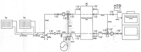
Our client from Sochi connected the hydraulic switch in the balancing manifold with two boilers at once. The main one is gas, the backup one is electric.

The outlet to the boiler in the BM-100-4D design complies with the DN 32 standard, that is, 1 1/4 inches. The thread is standard, suitable for the main types of pipes.

Polypropylene tees are placed on the return and supply. The three-part design was not chosen by chance. In the installation of pipes, tees are placed to enter additional communication. In the case of a hydraulic gun, the retraction principle also applies.
Advantages
Safely. Both boilers work correctly with optimal output
functional. The coolant is supplied in full and desired temperature(will not lose a degree).
practical. Two boilers in the heating system significantly reduce maintenance costs. The amount on the electricity bill is a pleasant surprise.
By the way, Esby three-way valves are used in the piping, also with polypropylene tees. An unusual design solution makes the boiler room even more efficient. Mixing of hot and cold streams occurs strictly in accordance with the norms of the throughput of consumers.
Also in the harness there is an indirect heating boiler of 200 liters, Grundfos 25/6 circulation pumps, floor heating automation. All of the above is connected in the balancing manifold Gidruss BM-100-4D

Three contours are directed downwards, one to the side. The center distance between the nozzles is 125 millimeters, which makes it possible to install pumping modular groups of both domestic and foreign brands.
balancing manifold made of structural low-alloy steel. This is the second brand after stainless steel, inferior to the "girlfriend" only in rust resistance. Signs of oxidation will appear after three to four years. To delay this unpleasant moment, all BM series collectors are painted with polymer paint. The composition has a light consistency, applied with a sprayer. Only 4 layers. The finish dries completely within a day. The product is then checked and prepared for shipment.
Learn more about the benefits of carbon steel manifolds at
Conclusions briefly

A hydraulic gun with two boilers is a reality.
Polypropylene tees can be used as wiring.
Several heating devices evenly distribute the load on the system, which significantly reduces the cost of diagnostics and maintenance.
Two boilers in one house is the key to the reliability of your heating system. It is very good if the second boiler is an alternative, for example, to gas. A gas boiler provides comfort (it does not require frequent maintenance), and a solid fuel boiler is installed to reduce heating costs and as a backup in case emergency. Subject to certain conditions they can be combined in one system. You can look at link an interesting video that shows two main ways to implement such a solution, or below is a brief summary and description of two ways to connect boilers into one system:
The first of the ways the implementation of such a solution is the use of a hydraulic separator or a hydraulic switch in the boiler piping scheme. This simple device serves to equalize temperatures and pressures in the heating system and allows you to combine two or more boilers into one system and use them both separately and in cascade - together.
One of the solutions for coordinating the operation of two heating units and heating system circuits


Hydraulic arrow (hydraulic separator) for connecting 2 boilers
Second option coordination of the operation of two boilers can be used in systems of low power and, for example, with a double-circuit gas heating boiler. Everything is simple here: two boilers are connected in parallel to each other, the circuits are separated from one another by check valves, while two boilers can work in one combination either separately or simultaneously.
The installation of a heating system in a private house begins with the installation of a boiler. In many suburban settlements there is no gas pipeline with natural gas. Instructions on how to properly connect a solid fuel boiler will alleviate this problem.
Necessary conditions for the correct connection of a solid fuel boiler to the heating system
- The room for the boiler room is selected separately. An area of about 7m 2. Boiler room in a separate building perfect option. Loading fuel into the boiler room can be facilitated. Sufficient in the receiving hopper area with outer side where it will be unloaded, for example, coal, to mount the so-called estrus. Having unloaded the fuel into the receiving bunker, the coal is poured down the slope into the boiler house independently.
- Position the heating boiler preferably below the 0 mark of the floor. This option installation of the boiler ensures ideal circulation of the coolant in the heating system without the use of a circulation pump.
- The base for the boiler must be made of a concrete pad with an even top layer. Thickness concrete screed 10 cm. The base area under the boiler must be 20 cm larger than the dimensions of the connected boiler. From the side of the furnace 40-50 cm.
- According to the norms of SNiP and fire requirements of the NPB, the distance between the boiler and the wall is 50 cm. From the side of the furnace hole, furnace, to the opposite wall, the distance is at least 1.3 m.
- The installed heating boiler must not have gaps between the base and the body.
- Connect the boiler to the heating system steel pipe at least 1 meter long at the inlet and outlet of the pipeline. Connect the boiler to the heating system with copper and polymer pipes not properly.
The scheme is applied below correct connection solid fuel boiler.
There are many connection methods. Consider one of the simple and reliable ways to connect.
A safety group is installed from the boiler on a direct pipeline. After the safety group, a tee for the bypass is installed. Further, the supply is connected to the wiring of the heating system. Having given up its heat in the heating system, the coolant returns to the boiler through the return pipe. To avoid the main disease in the operation of solid fuel boilers, condensate, which adversely affects the integrity of the boiler, a thermostatic three-way valve is installed, connected to the return line on the bypass, set to a temperature of 50-60 ° C. When heated, the coolant circulates through a small circuit through a three-way valve. A temperature of 55°C prevents the formation of condensate on the inner walls of the boiler. After the three-way thermostatic valve, a circulation pump is mounted. As soon as the return temperature reaches 55 ° C, the three-way valve opens, and the heated coolant rushes into the heating circuit to the radiators.
Connecting a solid fuel boiler paired with a gas boiler, diagrams and features
The scheme for connecting a solid fuel boiler in parallel with a gas boiler differs from the installation of two solid fuel boilers. The requirements for the boiler room also differ, where the main condition is air exchange:
- The area of a boiler room with a gas boiler, according to the recommendations of the fire authorities and the gas service, is calculated as follows: 1 kW of power - 0.2 m 3 with a ceiling height of 2.5 m, but not less than 15 m 3.
- A boiler room with a gas boiler must be equipped with a window with a window, the size of which is 0.03 m 2 per 1 m 3 of the volume of the room.
- The entrance door of the boiler room must go only to the street. Door width at least 80cm.
Gas boilers are available in two versions. Floor and wall. The requirements for installing a floor gas boiler are the same as for a solid fuel boiler. The length of the pipe connecting the chimney and the boiler is not more than 25 cm. If the boiler is coaxial, the pipe for the removal of combustion products is installed at an angle of -3 °. Otherwise, a separate pipe made of ceramic or lined with stainless steel with a hatch for removing combustion products is required for a gas boiler, and a tee with a tap for removing condensate is installed in the lower part of the pipe.
Gas and solid fuel boilers are connected in parallel to the heating system in several ways. The schemes are different, it is not necessary to know all of them, it is enough to understand the features that must be considered when using such a combination of boilers in relation to your room:
- Efficient use of the heat exchanger. It will separate the open heating circuit and the closed one. Connect the boiler to one of the circuits, and connect the second boiler to the second circuit. A solid fuel boiler, capable of raising the temperature of the coolant to 115 ° C, heats the secondary closed circuit to which the gas boiler is connected. The gas boiler is adjusted to a temperature of about 50-60 ° C. The solid fuel boiler will take on the main load. As the fuel burns out, the gas boiler will automatically turn on, which heats the secondary circuit of the heat exchanger. The secondary circuit is equipped with a diaphragm expander. The closed expansion tank protects the radiators from overpressure. With such a scheme of a connected solid fuel boiler, it is possible to install an open expansion tank directly in the boiler room under the ceiling.
- Using a hydraulic switch for parallel connection boilers are mainly used in houses with large area. The principle of operation of this system is as follows. The heating solid fuel boiler is installed first with a circulation pump, for example, 25/60 installed on the return pipe. On the pipe between the boiler and the pump is mounted solenoid valve MD regulating the operation of the boiler circulation. Mandatory installation of an adjusted safety valve in the supply line. Shut-off valves are not installed at the supply. The gas boiler is installed second. Through the tee, the boiler is connected through the supply pipe to the pipe from the solid fuel boiler and then connected to the hydraulic arrow. Shut-off valves are not installed on the arrow. On the second boiler, a pre-set safety valve. A closed expansion tank is installed from the hydraulic arrow on the return pipe to the tee. Then, through a tee on the pipe, it is connected first to the gas boiler with the installation of a circulation pump of less power than that of the first boiler. After the pump, a valve without a servomotor is installed. Further, a solid fuel boiler is connected from the tee on the return pipeline. The use of a collector after the hydraulic switch allows you to collect several heating circuits with pump groups on each of them. Collectors create the opportunity to configure each circuit individually according to the loads on the heating devices.
- Another method of parallel connection of boilers, when a solid fuel heating unit is installed first, a gas one is installed second, and between them a flap valve is installed on the supply pipe, operating in the direction from the first heating unit. Before the non-return valve, a bypass is installed, connected to a three-way thermostatic valve set to a temperature of 55 ° C. Between the thermostatic valve and the boiler, a circulation pump of greater power than in a gas one is installed on the return pipeline. The gas boiler is connected through a tee on the supply pipeline to the solid fuel boiler and then the supply pipeline goes to the radiators. The return pipeline from the radiators through a tee is first connected to the gas boiler. After the tee, it is necessary to install a spring check valve at the boiler. If both boilers are working at the same time, you need to set temperature regime on boilers. The gas boiler is set to 45°C. The solid fuel boiler is adjusted to a temperature of 75-80°C. Priority will be given to solid fuel. In the process of fuel combustion and temperature decrease in the first boiler, the gas boiler will turn on automatically and will maintain the set temperature in the house.
- The use of a buffer tank. The heat accumulator is a large steel insulated container, the task of which is to keep the heated coolant from the boiler. The maximum load occurs during the combustion of fuel in a solid fuel boiler. For effective work heating systems, the heat accumulator performs one of the main tasks. But there are big downsides to this scheme. In order to heat the radiators to the desired temperature, it takes from 2 to 4 hours. It is here that the gas boiler plays its leading role. Let's take a look at the installation diagram. The solid fuel boiler is tied in the traditional way. A safety group is installed in front of the bypass on the supply pipe. Then a bypass is installed through the tee. Further, the supply pipeline is connected to the storage tank. The bypass is connected to the return pipe through a thermostatic three-way valve set to 55°C. Then, a circulation pump is installed, working towards the boiler, and then the pipeline is connected to the boiler. A working circuit is created, and the coolant in the heat accumulator begins to gradually heat up. From the storage tank, the supply pipeline goes to heating appliances. A three-way valve is installed on it, going to the bypass. From the other outlet of the three-way valve, a circulation pump is mounted on the supply pipe.
After the pump, a flap valve is installed, working towards the radiators. Further, through the tee, the supply from the gas boiler is connected with the supply from the battery. After completing these works, the direct pipeline is connected to the distribution of the heating system. From the heating system, the return pipeline is connected through a tee to the gas boiler with the obligatory installation of a spring check valve operating towards the gas boiler. A closed expansion tank cuts in front of the tee, providing protection for the heating system. After the tee, through which the gas boiler is connected on the return, the return pipeline goes to the heat accumulator and is connected to the bypass from the supply pipeline also through the tee. After connecting to the bypass line, the return pipe is connected to the storage tank. This scheme allows you to quickly heat the heating system. Further operation of the system is designed for the priority of the operation of a solid fuel boiler.
Joint operation of a solid fuel boiler paired with an electric
The connection diagram of a solid fuel boiler in parallel with an electric boiler is described in detail and questions in the video:
Coordinated operation of solid fuel, gas and electric heating boilers
If desired, using a fairly simple connection scheme, you can combine the work of 3 or more various kinds heating boilers in addition to solid fuel, which still remains the most acceptable and economical in terms of the consumption of kindling resources.
We assemble the boiler room from A to Z...
Any boiler room is the heart of the system and. In this article I will tell you how to assemble a boiler room so that it at least has a well-functioning heating and water supply system. Using these algorithms, you can maximize the effect of the system.
Video:
I will teach you how to calculate and assemble such a heating system.
In this article you will learn:
Anyone who plans to supply natural gas to a boiler room should familiarize himself with the requirements for boiler rooms with gas boilers.
Any heating project where a house is planned to be heated begins with a calculation of the heat loss of a given house. About how to calculate houses, SNiPs, GOSTs and various literature have been developed for calculating heat losses. One of the SNiPs is SNiP II-3-79 "Construction Heat Engineering".
I want to talk a little about thermal calculations. In fact, the calculation of heat is not carried out by some devices, as some might assume. Any engineers at the design stage use pure or theoretical science, which allows, using only known materials from which the house is made, to calculate the heat lost. Many engineers use special programs to speed up, one of which I personally use.
The program is called: "Valtec Complex"
This program is absolutely free and can be downloaded from the Internet. To find this program, simply use the search in Yandex and enter the search line: "Valtec Complex Program". If you do not find this program on the Internet, then contact me and I will tell you the direct address. Just write in the comments on this page and I will answer there.
Solution.
For the solution, a universal formula is used:
W - energy, (W)
C - heat capacity of water, C \u003d 1163 W / (m 3 ° C)
Q - consumption, (m 3)
t1 - Cold water temperature
t2 - Hot water temperature
Just paste in our values, don't forget to take the units into account.
Answer: For each person, 322 W / h is needed.

Such a filter filters large crumbs in order to eliminate blockage in the boiler. The boiler with such a filter will last much longer than without it.
Also installed on the return line. But often they put it on the supply line.

The first reason why we put a check valve on the return line of the heating system.
The non-return valve serves to prevent the reverse movement of the coolant in cases where two boilers are installed in parallel. But this does not mean that it does not need to be put on the return line when one boiler is installed.
For the second reason a non-return valve is placed on the supply line, in order to exclude the reverse movement of the coolant in order to prevent debris from entering the heating system through the supply line.
How to connect two boilers

Maximum level of connection of two boilers with valves

Advantages of working two boilers in pairs
If one boiler fails, the heating system will continue to work.
You do not need to buy one powerful boiler, you can buy two weak boilers.
Two weak boilers working together give out much more heated coolant, since some powerful boilers have a small passage diameter. Due to the small passage diameter, the coolant flow through the boiler, to put it mildly, remains insufficient for big house. Although there are schemes that allow you to increase consumption. We'll talk about this below.
Disadvantages of two working boilers in pairs
The cost of two weak boilers is much higher than one powerful boiler.
Two pumps will not be justified. Although two pumps can work quite well in economy mode than one tuned for high speeds.
Regarding the selection of pipe diameter
As far as I know, there are three ways to determine:
Philistine way- this is the selection of the diameter by determining the speed of movement of water in the pipeline. That is, the diameter is selected so that the speed of water movement does not exceed 1 meter per second for heating. And for water supply it is possible and more. In short, they saw and copied somewhere, repeated the diameter. Also find all sorts of recommendations from experts. Some are taken into account average. In short, the philistine method is the most non-economic one, and the most malicious mistakes and violations are made in it.
Practice-acquired- this is a method in which schemes are already known and special tables have been developed in which all diameters are already available and additional parameters are indicated for the flow rate and speed of water movement. This method is usually suitable for dummies who do not understand calculations.
The scientific way is the most perfect calculation
This method is universal and makes it possible to determine the diameter for any task.
I watched a lot of tutorial videos, and tried to find calculations for determining the diameters of the pipeline. But I couldn't find a good explanation on the internet. Therefore, for more than 1 year on the Internet there has been my article on determining the diameter of the pipeline:
And someone generally uses special programs, according to the calculations of hydraulics. Moreover, I even found incorrect and unskilled hydraulic calculations. Which are still walking on the Internet and many continue to use an unreasonable method. In particular, the hydraulics of heating systems are not correctly considered.
To accurately determine the diameter, you need to understand the following:
And now attention!
The pump pushes the liquid through the pipe, and the pipe with all the turns gives resistance to movement.
The force of the pump and the force of resistance is measured by only one unit of measurement - these are meters. (meters of water column).
In order to push the liquid through the pipe, the pump must cope with the resistance force.
I developed an article that describes in detail:
Any pump has two parameters: head and flow. Therefore, all pumps have pressure-flow graphs, which show how the flow changes depending on the resistance of the liquid in the pipe.
To select a pump, it is necessary to know the resistance created in the pipe at a certain flow rate. You must first know how much liquid will need to be pumped per unit of time (flow rate). At the specified flow rate, find the resistance in the pipeline. Further, the pressure-flow characteristic of the pump will show whether such a pump is suitable for you or not.
In order to find resistance in the pipeline, the following articles have been developed:
At the design stage, you can find the consumption of the entire system, it is enough to know the heat loss of a particular building. This article describes the algorithm for calculating the coolant flow rate for certain heat losses:
Consider a simple problem
There is one boiler and a two-pipe dead end. See image.

Pay attention to the tees, they are indicated by numbers ... When explaining, I will indicate this: Tee1, tee2, tee3, etc. Also note that the costs and resistances in each branch are indicated.
Given:
Find:
| Diameters of pipelines of each branch Select the pressure and flow of the pump. |
Solution.
Find the total flow of the heating system.
We assume that the temperature of the supply line is 60 degrees, and the return line is 50 degrees.
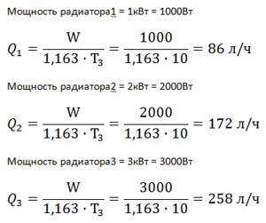
then, according to the formula

1.163 - heat capacity of water, W / (liter ° C)
W - power, W.
where T 3 \u003d T 1 -T 2 is the temperature difference between the supply and return pipelines.
The temperature difference is set from 5 to 20 degrees. The smaller the difference, the greater the flow rate and, accordingly, the diameter increases for this. If the temperature difference is greater, then the flow rate decreases and the pipe diameter may be smaller. That is, if you set the temperature difference to 20 degrees, then the flow rate will be less.
Find the diameter of the pipeline.
For clarity, it is necessary to bring the diagram into a block form.

Since the resistance in the tees is very small, it should not be taken into account when calculating the resistance in the system. Since the resistance of the length of the pipe will many times exceed the resistance in the tees. Well, if you are a pedant and want to calculate the resistance in a tee, then I recommend that in cases where the flow is more for a 90-degree turn, then use the angle. If less, then you can close your eyes to it. If the movement of the coolant is in a straight line, then the resistance is very small.
| Resistance1 = branch 1 from tee2 to tee7 Resistance2 = radiator branch2 from tee3 to tee8 Resistance3 = radiator branch3 from tee3 to tee8 Resistance4 = branch 4 from tee4 to tee9 Resistance5 = radiator branch5 from tee5 to tee10 Resistance6 = radiator branch6 from tee5 to tee10 Resistance7 = path from tee1 to tee2 Resistance8 = path of pipe from tee6 to tee7 Resistance9 = path of pipe from tee1 to tee4 Resistance10 = path from tee6 to tee9 Resistance11 = pipe path from tee2 to tee3 Resistance12= pipe path from tee8 to tee7 Resistance13 = path from tee4 to tee5 Resistance14= pipe path from tee10 to tee9 Main branch resistance = from tee1 to tee6 along the boiler line |
For each resistance, you need to choose a diameter. Each section of resistance has its own flow. For each resistance, it is necessary to set the declared flow rate depending on the heat loss.
Find the costs for each resistance.
To find the flow in resistance1, you need to find the flow in radiator1.
The calculation of the diameter selection is carried out cyclically:
Further calculations for this problem are laid out in another article:
Answer: The optimal minimum flow rate is: 20l/m. At a flow rate of 20 l / m, the resistance of the heating system is: 1m.
Of course, it is also necessary to take into account the resistance of the boiler, which can be taken as approximately 0.5 m. Depending on the diameter of the passage of the boiler itself. In general, to be more precise, it is necessary to calculate through the tubes in the boiler itself. How to do this is described here:
How to tie a water heating system for a very large house
Exists universal scheme for water heating systems, which allows you to make the system more perfect, functional and very productive.
Above, I already explained why these elements are needed:
Hydrogun- it's actually a hydraulic separator, detailed explanation and the calculation of hydraulic guns is explained here:
But I will repeat myself a little and explain some more details. Consider a diagram with a hydraulic separator and a manifold together.

V1 and V2 should not exceed the speed of 1 m / s with an increase in speed, unjustified resistance occurs at the inlet and outlet of the nozzles.
V3 should not exceed the speed of 0.5m/s, as the speed increases, resistance from one circuit to another comes into play.
F - The distance between the nozzles is not regulated and is taken as the minimum possible in order to comfortably connect various elements (100-500mm)
R- The vertical distance is also not regulated and is taken as a minimum of 100mm. Maximum up to 3 meters. But the distance (R) of the diameters of the four nozzles (D2) will be more correct.
The main purpose of the hydraulic arrow is to obtain an independent flow rate that will not affect the boiler flow rate.
The main purpose of the collector is to divide one stream into many streams so that the streams do not affect each other. That is, so that a change in one of the collector streams does not affect other streams. That is, a very slow movement of the coolant occurs in the collector. slow speed in the collector has less effect on the flows leaving it.
We disassemble the inlet diameter from the boiler D1
One of the calculations of the diameter is the following formula:
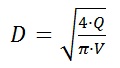
It is necessary to strive for the minimum speed of movement of the coolant. The faster the coolant moves, the higher the resistance to movement. The greater the resistance, the slower the coolant moves and the weaker the system heats up.
A task.
And let's try to increase the diameter to 32mm.
Then the schedule will look like this.

Maximum consumption 29 l/m. The difference from the original to 4l / m.
It's up to you to decide whether the game is worth the candle ... Further increase will lead to a waste of money on a large diameter.
Further, I take into account that there will be a flow rate of 29 l / m from each boiler. the consumption from two boilers will be equal to 58 l / m. Now I want to calculate what diameter to choose for the pipe connecting two boilers and entering the hydraulic arrow.
Finding the diameter after the tee
Given:
At a flow rate of 58 l / m, the resistance was: 0.85 m, basically the resistance creates about 0.7 m. To reduce the resistance of the sump filter, it is enough to increase its diameter or thread on it. The greater the permeability of the sump filter, the less resistance in it.
Therefore, we make a decision: Do not increase the diameter, but increase the sump filter, with a thread of up to 1.5 inches.
With this effect, we will significantly increase the total heat flow from the boiler to the hydraulic gun.
Also, by this effect of increasing the flow through the boiler, we increase the efficiency of boilers.
Also, if we want to reduce the resistance of the check valve, then the thread on it should be increased. Therefore, we accept with a thread of 1.25 inches.
Ball valves should be selected in such a way that the internal passage does not narrow or increase, but exactly repeats the passage itself. Choose a passage in the direction of increasing diameter.
More about hydroguns:
According to the task:

Consumption of warm floors: 3439 l/h at a temperature difference of 10 degrees.
400m 2 x 100W / m 2 \u003d 40000 W
As for radiator heating, the principle of operation of various schemes. I have not yet prepared articles on this topic, since most people know how to do this, at least approximately. But there are plans to touch on this topic, and to prescribe strict laws and calculations for the development of schemes in space.
As for warm water floors
The diagram shows that warm water floors are connected through. The circuit through the three-way valve forms.
mixing unit is a special piping chain that forms the mixing of two different streams. In this case, for there is a mixing of two streams: the heated coolant from the collector and the cooled coolant returned from the warm floors. Such a mixture, firstly, gives a lower temperature, and secondly, it adds consumption to warm floors. Additional flow accelerates the flow of coolant through the pipes.
Engineering calculation of diameters for the required flow
For these calculations, I developed a section:
How to get rid of air in the heating system in a constant mode?
The most ideal way to get rid of air in automatic mode serves as an element: Automatic air vent. But for its effective use, it must be installed on the highest supply pipeline of heating systems. In addition, you need to create an area of \u200b\u200bspace in which air will be separated.
See diagram:
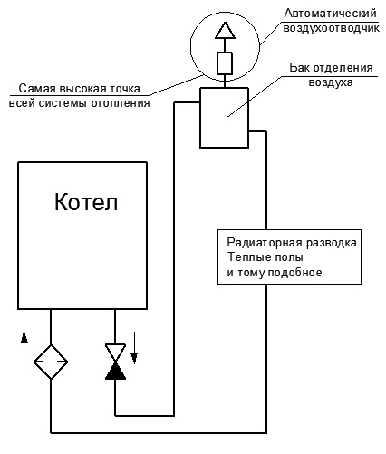
That is, the outgoing coolant from the boiler must first of all rush upward to the air separation system. The air separation system consists of a tank with a thickness larger diameter 6-10 times the branch pipe included in it. The air separator tank itself must be at the highest point. The top of the tank should be .
The inlet pipe should be at the top, and the outlet from it at the bottom.
When the coolant has a low pressure, then the gases in it begin to be released. Also, the hottest coolant has a more intense outgassing.
That is, by driving the coolant to the very top, we reduce its pressure and thereby the air begins to be released more intensively. Since the coolant immediately going to the air separator tank has the highest temperature and, accordingly, gas evolution will be intense.
Therefore, for ideal air release in the heating system, two conditions must be met: These are high temperature and low pressure. The lowest pressure is at the highest point.
For example, you can try to install a pump after the air separator tank, thereby reducing the pressure in the tank.
And why is this method of air release not used everywhere?
This method of air release has long been known!!! In addition, it removes the hassle of air release by an order of magnitude.
How to connect a solid fuel boiler
As is known solid fuel boilers are at risk of overheating due to the failure of air shut-off mechanisms. For the safe use of solid fuel boilers for heating systems from high temperatures, two main elements are used.
How a capacitive low loss header works is described here:
Why are high temperatures dangerous for heating systems?
If you have plastic pipes such as polypropylene, metal-plastic and, then direct connections of such pipes to a solid fuel boiler are contraindicated for you.
The solid fuel boiler is connected only with steel and copper pipes capable of withstanding temperatures over 100 degrees.
Pipes that can withstand high temperatures are assembled with a temperature limit.
Three-way valves are mainly used with large bores and servomotors. with mechanical movement of valves have a very narrow bore, so check the flow charts of these three-way valves.
A three-way valve in the boiler circuit serves to prevent low temperature With . Such a three-way must let the coolant into the boiler at least 50 degrees.
That is, if the heating system is below 30 degrees, then it begins to open the boiler circuit inside the boiler itself. That is, the outgoing coolant from the boiler immediately enters the boiler on the return line. If the boiler temperature is above 50 degrees, it starts to start the cold coolant from (from the tank). This is necessary in order not to cause a strong overload in temperature in the boiler circuit, since a large temperature difference causes condensate on the walls of the heat exchanger, and also reduces the favorable annealing of firewood. In this mode, the boiler will last longer. Also, the ignition of the boiler will be faster and more efficient than if the boiler was constantly supplied with ice coolant.
The temperature of the solid fuel boiler must be at least 50 degrees. Otherwise, it is necessary to reduce the temperature of the three-way valve not to 50, but below degrees to 30.
With a low temperature heating of 50 degrees, a decrease in the temperature of the three-way valves must be taken into account. If you set 50 degrees on the boiler, then set 20-30 degrees on the three-way valve of the boiler circuit, and 50 degrees at the outlet. Also note that the higher the temperature difference in the boiler, the higher the efficiency of the boiler. That is, a cooler coolant should flow into the boiler. Also, the greater the flow through the boiler, the higher the efficiency of the boiler. Thermal engineering testifies to it.
The flow through the boiler must be as high as possible for efficient heat exchange (efficiency is higher.).
A three-way valve at the outlet to the heat consumer is needed in order to stabilize the temperature of the consumer and prevent high temperatures from entering.
For example, from a real object:


This article is over, write comments.
This material belongs to the section: Constructor of water heating
| If you would like to receive notifications about new useful articles from the section: Plumbing, water supply, heating, then leave your name and email. |
New Articles
- Russian-Portuguese phrasebook for tourists (travelers) with pronunciation
- Portuguese for tourists
- What are the main differences between Spanish in Spain and Latin America?
- Danish-Russian online translators Danish language translator
- What is the difference between Portuguese and Spanish
- Transiting Saturn Opposition Natal Saturn Moon-Saturn Opposition in Radix Male
- Horoscope of work and money
- Protection from the evil eye and envy will help save what is expensive. How to put protection from
- What does it mean if you have a dream within a dream?
- Chinese horoscope Ox (Ox)
Popular Articles
- Herbal teas for sore throat
- What to do with diarrhea and temperature in an adult
- Fortune telling on wax: the correct interpretation of the figures The procedure for conducting fortune telling
- Moon Pisces Compatibility Who suits a woman with the moon in Pisces
- What does a Scorpio love about sex?
- I dreamed of a neighbor descending from the stepladder along the vanga
- Short Course in Theoretical Mechanics
- Preparation for the exam in mathematics (profile level): tasks, solutions and explanations
- Sophia-Assumption Cathedral in Tobolsk
- The Poltava diocese confirmed its loyalty to the canonical Ukrainian Orthodox Church